
Well, the first issue with this TR-7 was that the digital frequency display was not working. This was a particular issue because the bulbs that backlight the “analogue” frequency scale on the VFO and the S meter had also failed, so it was pretty challenging to figure out where the rig was tuned!
The display fault was quite bizarre at first, until you come to an understanding of how the frequency display works. The display was showing a constant frequency of 51.950 MHz when set to read the operating frequency and the display was blanking when set to read an external frequency from the socket on the rear panel – as it should when no input is present.
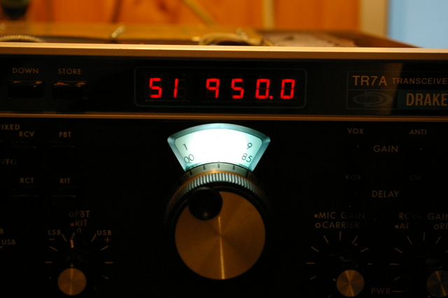
Some who saw this fault pondered that it could be displaying some sort of error code, but there’s nothing in a TR-7a of sufficient intelligence to generate such things. This really is just a simple frequency counter using logic chips – a mixture of TTL, ECL and CMOS, just to add variety!
The answer to the strange reading lies with how the counter compensates for the rig’s first IF. The counter counts the frequency of the LO that feeds the first mixer, which upconverts to the first IF of 48.05 MHz. The counter frequency is therefore always offset 48.05 MHz above the signal frequency to which the radio is tuned. So, how do you easily subtract 48.05 from the displayed value to arrive at the correct frequency display? The answer is that the decade counters that count cycles of the LO are preloaded to 519500 at the start of each counting cycle. When the count reaches 1000000, after 480500 cycles, the decade counters “wrap around” to zero. The count will then continue until the display is indicating the operating frequency, effectively subtracting the IF but without any arithmetic that would be cumbersome to achieve with discrete logic chips.
The fault turned out to be the failure of U9013, a 10138 ECL counter IC that forms part of the prescaler to the frequency counter, meaning that the display wasn’t counting at all, just displaying the seemingly bizarre value which it preloads at the start of each counting cycle. I desoldered the old IC and fitted a new one in a DIL socket, making any further changes a little easier! Fortunately, I found an Ebay seller who stocks “new old stock” items of this long-obsolete IC at sensible prices.
I thought about replacing the display backlights with incandescent bulbs. Often this is the best way with a vintage radio as they don’t all look good with LED light behind the meters but I felt that the TR-7 was an exception. It is quite a “futuristic” looking rig and the blue meters look fantastic with white LEDs backlighting them, in my opinion. There is also a second advantage to this route, in that the VFO backlight is quite close to the oscillator itself, so minimising the heat output of any backlight helps to stabilise the VFO.
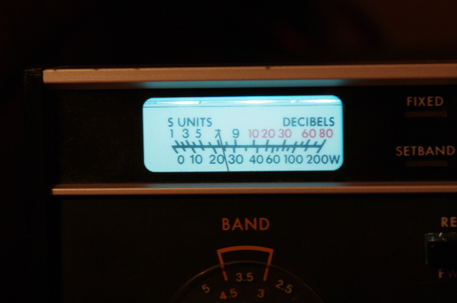
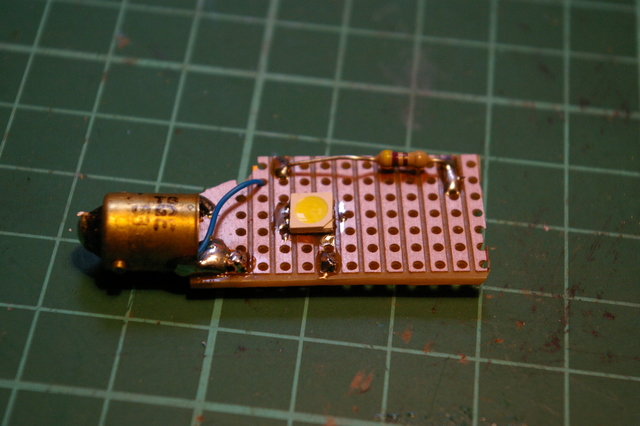
I used a few high intensity white LEDs from a tape of LED kitchen lighing strip for the backlights – 3 LEDs on a tape behind the S meter and a fourth built onto a bit of veroboard soldered into the base of the old bulb behind the VFO scale. I think the rig looks great with this new illumination!
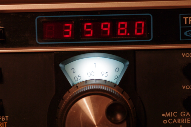
With these few faults fixed I went through an alignment of the radio and it started to come to life. There was good transmit output and receiver sensitivity on all bands, and all features seemed to work. Just occasionally, though, it would mute, or the carrier oscillator would dart off frequency. In addition, it would sometimes send the power supply into shutdown on the peaks of modulation during SSB transmission.
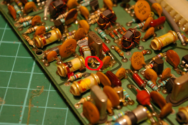
The former problem I found by prodding at each of the cards in the radio, looking for evidence of an intermittent connection. I eventually found a bit of intermittency on the ” PBT / Reference” board. I pulled the board out and eventually spotted a location where the wire on an inductor looked very close to the can of an adjacent crystal. I remade the solder joint and added a blob of “hot melt” glue between the components to keep them separated and this did the trick.
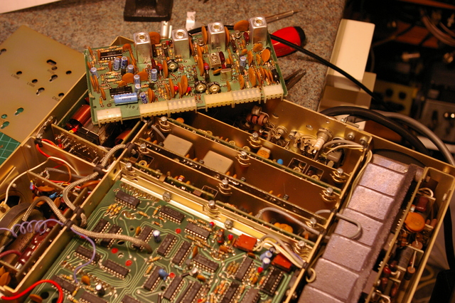
One of the nice features of the TR-7 is that it is constructed using “plug-in” PCBs which can easily be removed to be worked on. This modular construction technique does have some disadvantages in that it becomes less easy to “prod” around with a ‘scope probe when troubleshooting, and extender cards tend to be impossible to come by. In comparison to modern rigs, though, with only a couple of large PCBs that tend to be very difficult to remove from the radio, I quite like how the TR-7 is put together from a maintenance perspective.
The remaining issue, of occasional shutdown of the power supply, I traced to the current limiting function of the power supply. This shuts down the PSU if the current draw exceeds 25 Amps. I used a large rheostat and a DC current clamp meter to load the supply to rated output and determined that the power supply was doing what it is specified to do, and that the current limiting was operating at about 25 Amps. I had wondered if the shunt resistors had drifted high and made the current limiting a little too sensitive, but not so.
This points the finger at the main consumer of current from the PSU, the power amplifier stage in the radio. I traced the signal using an oscilloscope through the pre-driver, driver and power amplifier stages. I discovered that the PA itself was being driven with a very distorted waveform and the culprit was the pre-driver stage, which appeared to be drawing no bias, so it was operating in class C. I believe that the distorted drive to the main PA was causing it to work much harder than required to achieve the required power level after the low pass filters due to the excessive harmonic content in the drive signal. I reworked the rather basic bias circuitry in the pre-driver to give it the correct ioperating conditions and this appears to have resolved the issue.
The radio is now ready for a bit of on-air testing to see if any other gremlins appear!