I quickly came to the conclusion that all of the “modifications” had to go before I could easily work on this radio. This was partially due to the extra components physically restricting access to areas of the radio, and partially because it was easier to just remove them than to try and figure out what they were trying to achieve. Of course, there’s no guarantee that the mods ever actually worked properly anyway! In any case, I can always re-instate them once the basic radio is working to spec if required.
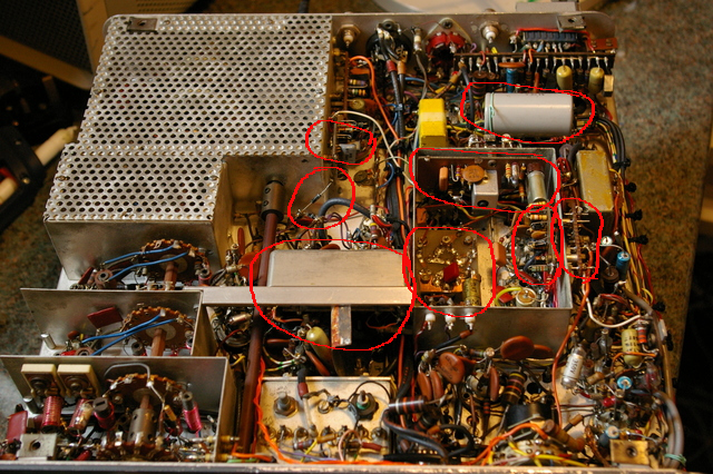
It turns out that what had been added was a replacement VOX circuit, an additional Collins mechanical filter for CW, and an additional carrier oscillator for CW which, curiously, was only active in transmit. I could have understood the addition of a CW carrier oscillator if it had been required to position the passband correctly on receive for the CW filter, but CW RX was using the normal USB carrier oscillator! Why go to all this effort in the transmit path?
Maybe the keying of the audio oscillator that generates the normal CW had poor characteristics?
Of course, there was then circuitry to switch between the original and new carrier oscillators, to key the output of the new oscillator, relays to switch the IF filtering between filters and a DC supply for the additional circuitry which was all solid state.
The TX muting signal had also been split into two legs, disabling some stages in CW TX but enabling them in SSB. What a muddle!
The biasing and screen supplies for the PA had been changed as well. Maybe this was an attempt to run it in class C on CW?
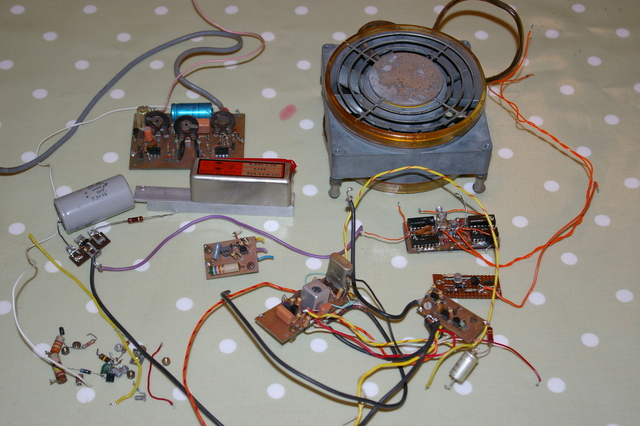
Anyway, here’s a photo of the bits I removed during this process. Almost enough to make another radio!
I’m not entirely sure I’ve got the radio back to “standard” configuration as there are a few extra parts in the carrier oscillator and modulator enclosure that look original yet aren’t on my circuit diagram, but it’s a start and these parts don’t appear to be causing any problems, so they can stay as is for now.
At any rate, after a few false starts I had the radio receiving again so I turned my attention to the TX chain. Having put the PA grid and screen circuits back to standard I couldn’t set the PA bias to achieve any significant standing current as the grid bias was only variable up to about -65 to -70 volts. The 8k2 resistor in the PSU bias setting divider had drifted a little high so I replaced it and added another 15k in parallel to give me a more usable adjustment range that works with the valves I have.
I had to restore the link between the tone oscillator and the mic gain control to get the Tune function to work again but soon found that it would develop about 100W key down on the 80m band, which is encouraging. I hooked up my MC60 microphone with internal preamp and it’ll whistle up to about 80W on SSB and a very quick test against an SDR receiver suggested that the audio sounds quite good and there isn’t horrendous splatter either side of the signal. This rig does need the high output of an old-fashioned high impedance microphone, or a modern mic with a built in preamp, to give its best.
It could all do with more gain on TX, but I’m sure the removal of all the mods has probably put a few stages out of tune, and, of course, it’s possible the Kokusai filter has become a bit lossy with age, but an encouraging few hours work.
I was tuning around the 80m band, contemplating trying for a “first QSO” when I came across Steve, G3ZPS. Given that it was a conversation with him that sent me down the road of acquiring this radio in earnest, it seemed fitting that he be given the honour of its’ first QSO.
By all accounts, he had his work cut out chasing me up and down the band! The radio wasn’t so much drifting but each switch between transmit and receive appeared to cause the VFO to randomly shift a couple of hundred hertz in frequency!
Well, some work to do, but, it’s encouraging to have got this far!
Keep an eye on this page for further updates!