
I recently picked up this amplifier second hand and have found very little information about it on line. I started this page in the hope that I can share information that others might find useful. The only other significant mention of these amplifiers I’ve been able to find has been on VE3DDQ’s page.
General Description
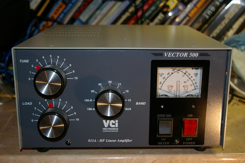
The Vector 500 is a linear amplifier covering all HF bands from 160 to 10 metres. It is based on four parallel 811a valves in a grounded grid configuration although my example has had 572bs fitted at some point. The valve grids are tied directly to chassis ground, bias being applied, along with the HT negative connection, via a centre tap in the heater winding.
Heaters are supplied by a 12.6 Volt winding, with pairs of valves having their heaters supplied in series. The heaters are fed through a choke consisting of 24 bifilar turns of enameled wire on 3 small ferrite cores glued together, and located low in the chassis immediately behind the rear panel.
The RF drive signal is fed through a fixed C-L-C Pi matching network for each band, selected by two wafers on the band switch, to the cathode / heater pins of each valve via coupling capacitors. The valve bases, all feed circuitry, the antenna changeover relays and keying and ALC circuitry is mounted on a vertical printed circuit board located behind the rear panel.
The HT supply of approximately 1750 Volts DC is generated by bridge rectification of the output of a mains transformer winding. Each leg of the bridge rectifier consists of three series connected 1N5408 diodes. A series combination of 5 220uF 400V reservoir capacitors provides the smoothing, with each capacitor shunted by a 270k equalising resistor. The current exiting the bottom end of the equalising resistor chain feeds the anode voltage meter via an adjustable shunt resistor. The above circuitry plus meter shunts for the grid and anode current indication is mounted on a vertical PCB to the rear of the mains transformer on the right hand side of the chassis. HT feed to the anodes is provided via a fault current limiting resistor, decoupling capacitors and a large choke located between the four valves.
The anode network is a conventional C-L-C Pi network fed from the anodes via a DC blocking capacitor. The tank coil for 10 through 20 M comprises an air spaced coil mounted above the band switch with switched tappings whilst on the lower bands, additional inductance is provided by a tapped coil wound on a ferrite toroid below the band switch. In addition, padding capacitors for tune and load are switched into circuit by wafers on the band switch for the lower bands. Tuning and loading adjustments are provided by variable capacitors driven by Jackson reduction drives.
The signal at the anode end of the tank circuit is sampled by a small network of capacitors and fed to a few turns of wire on the heater choke in order to provide neutralisation of the amplifier.
The drive signal to the valve cathodes is sampled by a diode detector and, as it exceeds a threshold determined by a potentiometer adjustable on the rear panel, provides a negative going ALC signal to the exciter.
Metering is by a cross needle dual metering movement, with the left hand meter displaying anode current and the right hand meter switchable between anode voltage and grid current.
An auxiliary winding on the transformer feeds a rectifier providing a DC supply of approximately 30V which feeds the antenna changeover relays. These are fed from a two transistor drive circuit which reduces the current draw on the PTT line from the exciter to negligible levels. The transistor, which switches the antenna relays, also grounds the centre tap of the heater winding on transmit via a series chain of 2 diodes, which establish the bias conditions for the tubes during transmit. When receiving, the relays pull the cathode to a positive DC potential relative to the grids, cutting off the valves.
A 12 Volt regulator fed from this auxiliary supply feeds the meter illumination bulb and a fan mounted on the partition between the valve compartment and that housing the mains transformer and HT rectifier board.
The anode current meter shows a standing current of approximately 100mA when the amplifier is keyed without drive power.
The incoming mains connection (for 240V) features 6 Amp fuses on both the live and neutral lines, which then pass through separate chassis interlock microswitches to the double pole front panel mains switch and then to the mains transformer primary.
Another interlock switch grounds the HT supply rail when the chassis is opened.
The mains transformer primary has a number of tappings for selecting the input voltage which have not been investigated. This unit bears a label indicating it is configured for a 240V supply and such a mains input results in about 6 Volts at each of the valve heaters and 1750 Volts indicated HT under conditions of no load.
Keying interface
The keying line from rig to amplifier should present no problems for most modern radios to drive. The line floats to about +30V DC in the inactive state and sinks about 2.5 mA when grounded to bring the amplifier into transmit.
Schematic
I have traced out the schematic in order to aid my own troubleshooting. I take no responsibility for any errors or omissions in this document – I’m sure there are many currently! I will attempt to update it as I discover errors or learn more about this amplifier but hopefully it will help anyone else who is searching for information on this amplifier. Since I was mostly concerned about the control and monitoring side of the amplifier, I have simplified the RF circuit to show only input and anode components for a single band and omitted the band switching and mains input side.
Maybe I’ll get round to doing a more comprehensive job one day! Until then, the schematic as it stands can be found at the following link:
User Manual
The manual for my amplifier turned up eventually and the previous owner kindly forwarded it to me. After going to the effort of tracing out the schematic, I was delighted to find one in the manual! I’ve scanned the manual and it’s available here:
There will be more information to come, so please check this site for updates if you find it useful.