
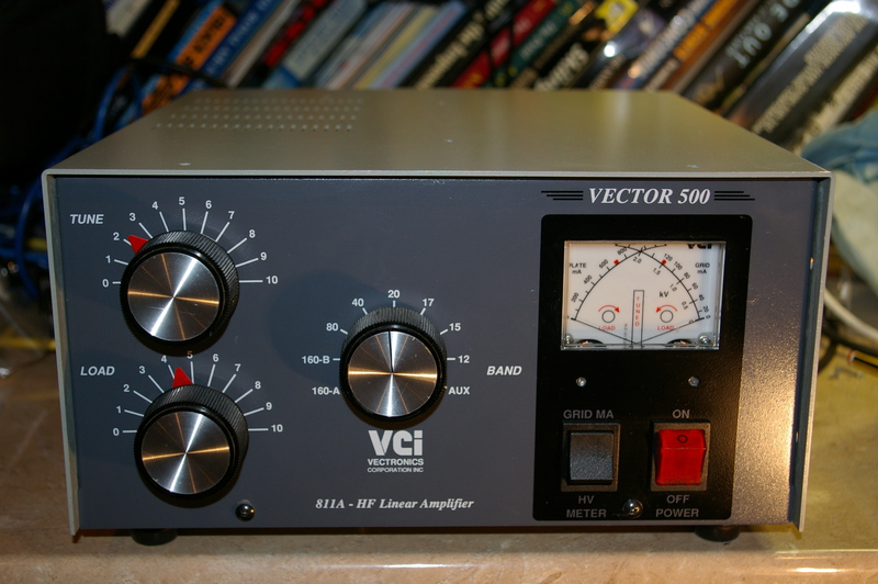
I don’t recall ever seeing one of these in the UK before and there is precious little information about them online. Vectronics appear to have been a Canadian company who were active in the ’90’s but, like many, got absorbed by MFJ and disappeared…
It’s a HF linear using four 811a valves in grounded grid configuration – so a “budget” level linear similar to the Ameritron AL-811H. 811s are quite fragile and not an ideal choice, perhaps. Nevertheless, it was offered at a very reasonable price and I fancied a new project for the winter months!
Perhaps by way of a warning, it came with a shoe box containing a set of 811s in various states of destruction ranging from one with just a small silvered patch on the anode where it had started to melt to one where the glass envelope had melted, a small hole had appeared and the vacuum “escaped”, with a bang, no doubt!
Upon opening the amp, I was, therefore, delighted to find it populated with a mint looking set of 4 572b valves. These are pretty much a plug-in replacement for the 811 but with much larger carbon anodes capable of dissipating almost 3 times as much power! It really ought to just loaf along at the 400W UK legal limit in this configuration.
I should say at this point that working on amplifiers like this can be lethal if the correct safety procedures are not followed. A DC supply of 1800 Volts at nearly an Amp will kill you if you make one simple mistake. It’s as simple as that. There is no reason to operate such an amplifier with the covers removed because any issues can be deduced by a combination of watching the meters when fully assembled and by testing “cold”, without power, using low power RF sources, when stripped down. I recount my experiences here for the use of those who are suitably skilled and take no responsibility for any eventualities.
I powered the amp up initially using a “dim bulb” tester, just in case of problems. I expected a 100W light bulb to illuminate fully with the filament load on the amplifier but, to my surprise, the HT meter gently rose to 1500 Volts, the fan started and the bulb almost extinguished.
On investigation, I found a burnt out heater choke which was shorted out but, mercifully, its connection to the PCB had unsoldered itself before it took the mains transformer out, hence no load from the filaments! At least I knew the HT supply could support almost full voltage without drama!

I purchased a longer ferrite rod and wound a new heater choke using the same number of turns (24, wound bifilar) using thicker gauge wire more able to withstand the 8 Amps of heater current. My new choke managed about 28uH of inductance – not fantastic, but enough, especially as I can’t foresee this getting much use on top band. On reassembly I found that the amplifier worked OK on the lower bands but gave poor output on 20M and above and tended to “take off” quite readily.
It was while updating this blog that the issue occurred to me. The white wire in the picture above is a neutralisation winding of 4 turns on the filament choke that is fed by a signal “sniffed” from the hot end of the anode tuning capacitor via 8 pF of capacitance. The idea is that it nulls out coupling of the amplifier’s output to the input, which occurs by inter-electrode capacitance, by coupling in a small proportion of the output signal to the input 180 degrees out of phase. I had used a different picture taken during disassembly to correctly (so I thought!) locate this coil on my new choke but I’d got it 180 degrees out of phase! The above photo showed it more clearly. It always pays to take plenty of photos when dismantling equipment!
To double check, I performed a cold neutralisation check with the amplifier powered down. I connected a 4k resistor from the anodes to ground, to simulate the anode driving impedance, then fed a signal generator backwards into the output of the amplifier, bypassing the antenna relays. An MFJ antenna analyser makes a very handy RF source for this task if you don’t have a signal generator. The input of the amplifier was terminated with a 47 ohm resistor and an oscilloscope used to look at the RF signal on the valve cathodes against the (grounded) grids. With the output tank tuned for “maximum smoke”, sure enough, there was a significant signal coupled into the grids, and it got slightly less when I shorted out the neutralisation winding, showing that it was indeed working in the incorrect sense!
Upon winding the neutralisation coil the correct way onto the filament choke I found a couple of extra turns were necessary for the best nulling of the parasitic signal appearing on the cathode. Maybe this was due to a difference in characteristics between the 811a and the 572b tubes, or perhaps my filament choke had slightly different properties compared to the original?
Another issue I found when checking this amplifier concerned the protection diodes for the meter shunts. There are a pair of 1N5405s in series across the anode and grid current metering shunts. The idea of these diodes appears to be to protect the meters and shunts from a flashover in the valve or tank circuit. If excessive current is drawn from the HT supply to ground, these become forward biased as the drop across the meter shunts increases and divert the current returning to the HT supply negative rail around the shunts. I found that these diodes were connected in series but with the polarities reversed. They wouldn’t have done anything until one of them went into breakdown by which time both meters and shunts would have been long gone. As it happens, somebody had “been here before” and replaced the 10 ohm grid current meter shunt with an overkill series-parallel network of 4 3 watt wire wound resistors, so perhaps this resistor had been subjected to damage due to the incorrectly oriented diode? I fixed the orientation of the diode and replaced the shunt resistor with a neater, more conservatively rated part.
On initial testing, once the few issues with the amplifier had been sorted out, I found it would make approximately 600 Watts output with a constant carrier on all bands. To do so it needs approximately 50 Watts of drive from my Elecraft K2 and draws about 650 mA anode current and 60mA grid current. It is easy to tune and doesn’t appear to have any vices – into a dummy load, at any rate! I don’t currently have an antenna system that will cope with this amplifier’s full output at home, so testing on air will have to wait until another time.
I’m very happy with this. It makes the UK full legal power limit with a little margin. Yes, a quad of 572bs could make much more power, or the same power could be made using just two tubes, but either would require a higher HT supply voltage, so a new mains transformer. As it stands, the compact nature of this amp would probably mean that it has cooling issues dissipating any more heat and, with the 572bs being driven very conservatively, it should be quite forgiving and reliable.
Watch this space for further updates on my progress with this amplifier!
Meanwhile, in view of the lack of information online about the Vector 500, I’ve started this page to share anything I discover.