
It all started when my wife took a shine to my cousin’s Nixie clock when visiting. “Could you make me one?”, she asked. Well, yes, I could… but most of the designs I could find relied on obsolete TTL logic chips and had very basic functionality. I felt that I could do better than that. So commenced another project…
Nixie tubes are a predecessor of Vacuum Fluorescent displays, themselves a predecessor of 7 Segment LED displays, which were a predecessor of Liquid Crystal displays and so on.. You get the picture. They date from the mid 1950s as a technology for the electronic display of numerical information and were found in early electronic calculators and laboratory instruments, among other applications.
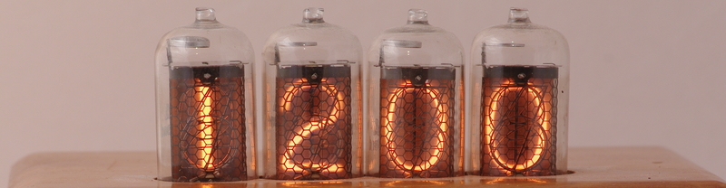
Despite their age, there is something attractive about the nicely rounded typography and the warm orange glow of a Nixie tube . They are also very easy to read from a distance and a bit of a talking point these days. Gone are the days of my childhood when every petrol pump was stuffed full of them. This actually makes them very suitable for a living room clock in my opinion.
Some weeks later, my wife returned from an antiques shop with a couple of old cigarette cases, ideal for housing such a device. The idea clearly wasn’t going to go away, but what about those old TTL chips?

The problem with making a clock out of logic chips is that the functionality is inherently limited and setting the time is a fiddly and time consuming operation. There is also little scope for adding other features such as displaying the date and synchronisation with a time standard. At the same time, I had been playing around with PIC devices, so this presented an opportunity to do something useful with one.
Nixie tubes have quite awkward drive requirements, in that they need up to about 170 volts between the anode mesh in front of the digits and the cathode wires, which form the shape of the digits themselves, in order to “strike” the orange glow. The current then needs to be limited to a few milliamps per segment. They also take a few milliseconds to “strike” so multiplexed drive arrangements often aren’t that successful and, in any case, I wanted to avoid any visible flicker.
The bottom line is that I needed to drive the 40 segments of the nixie tubes with individual open collector drivers that could withstand over 170 volts. I looked at a number of driver ICs which could withstand up to about 60 volts. Whilst there are some “tricks” one can employ to use such drivers with nixie tubes, due to their unique characteristics, they also didn’t appear to be very readily available, and, even then, only in surface mount packages.
I ended up with a chain of 5 74HC595 8 bit shift registers to expand the PIC’s IO to cover the required 40 outputs, with each segment driven by a separate MPSA42 300V rated NPN transistor.

The project was wired up point-to-point on veroboard. The underside had got quite “busy” by the time I had finished. Needless to say, it was this project which convinced me that it was about time I taught myself how to design my own PCBs!

In terms of the firmware the requirements, initially, at least, were quite simple:
- Maintain a count of seconds, minutes and hours
- Divide the 4MHz clock frequency to derive a 1Hz clock to increment the seconds
- Provide a means to set the time
- Shift the drive signals for the nixie segments out into the shift register chain each time the digits are updated
For setting the time I settled on two pushbuttons that cycle through setting the hours, minutes and zeroing the seconds in the style of a traditional digital watch. I also added a mode whereby the display is blanked which can be activated when away on holiday to extend the life of the tubes, or when somebody is sleeping in the room with the clock.
I provided a backup battery to maintain the correct time during power cuts. An input pin on the PIC is used to detect power failure and, in response, remove drive to the output pins and disable all but the timekeeping code to minimise power consumption.
Most nixie clock designs available on the internet power the nixies from a DC HT supply derived either from a mains transformer or even direct from the mains supply. Since the clock was to be in the living area of the house I wanted to avoid mains power on safety grounds and space was quite tight in the box in any case. I elected to power the clock from 12V DC delivered by a “wall wart” mains adaptor. I built a switched mode boost converter based on the MC32063 to provide the HT supply for the nixie tubes.
The clock has now been operational for over 10 years without a hitch. There has been no noticeable degradation in the ITT GNP-17A nixie tubes during that time and I fully expect the clock to live for many more years. Whether I’ll ever get round to adding synchronisation to a frequency standard or any of the other features that the PIC based solution makes possible is another matter!